standing wave ratio (SWR)

What is standing wave ratio (SWR)?
Standing wave ratio (SWR) is the ratio of the maximum magnitude or amplitude of a standing wave to its minimum magnitude. It indicates whether there is an impedance mismatch between the load and the internal impedance on a radio frequency (RF) transmission line, or waveguide. Such mismatches indicate that there are standing waves along the line that can reduce its power transmission efficiency.
What are standing waves?
Standing waves, first observed by scientist Michael Faraday in the 19th century, represent the power that the transmission line has not accepted. These unwanted waves are reflected along the line, affecting its transmission efficiency and reducing the power that finally gets transmitted.
A standing wave is the combination of these waves moving in opposite directions and with the same amplitude and frequency. Since the waves are "superimposed" on each other, interference is created and their energies (voltage or current) are either added or canceled out by each other.
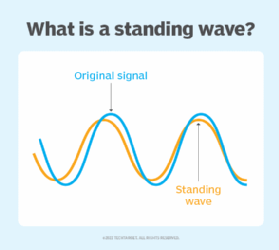
Standing waves are created when a transmission line does not terminate correctly. As a result, the traveling wave (also known as the incident wave) gets reflected -- completely or partially -- at the receiving end. Together, the incident and reflected waves give rise to standing waves along the line.
At some points along the transmission line, the two waves (or signals) are in phase, so they add together, leading to maximum voltage and current. These points are known as the voltage or current maxima.
At other points, the two waves are out of phase, so the resultant voltage and current will fall to the minimum (voltage or current minima). Ultimately, the amplitude of standing waves indicates the amount of reflection along the transmission line.
How standing waves work
In real-world conditions, the load on the transmission line, or waveguide, does not absorb all the RF power that reaches it. This power is known as the forward power.
Instead, some power is sent back toward the signal source when the signal reaches the point where the line connects to the load. This is the reflected power or reverse power. The reflected power and forward power together set up a pattern of voltage and current maxima (loops) and minima (nodes) on the line. These patterns are known as standing waves.
Standing wave ratio (SWR) explained
The SWR, then, is the ratio of the following:
- the RF voltage at a loop (maxima) to the RF voltage at a node (minima); or
- the ratio of the RF current at a loop (maxima) to the RF current at a node (minima).
The highest SWR value – i.e., an infinite and, thus, undesirable value -- occurs when no load is connected to the end of the line, meaning the line is unterminated. This can happen when the end of the line is either short-circuited or simply left open (open circuit). A high SWR indicates that there are extreme voltages and currents at certain points on the line.
Sometimes, a moderately high SWR does not produce significant power loss or line overheating and can be tolerated. Such situations may occur at relatively low RF frequencies and low RF power levels as well as at short lengths of low-loss transmission lines.
Mathematical expression of standing wave ratio
When SWR refers to the ratio of forward and reflected voltages, it is known as voltage standing wave ratio, or VSWR. VSWR is the ratio of the maximum voltage magnitude to minimum voltage magnitude on a lossless line.
If the following is true:
i = incident wave and r = reflected wave
And the following is true:
V = voltage and |V| = voltage magnitude
Then the following is also true:
|Vmax| = |Vi| + |Vr| and |Vmin| = |Vi| - |Vr|
|Imax| = |Ii| + |Ir| and |Imin| = |Ii| - |Ir|
VSWR = |Vmax|
|Vmin|
Similarly, the Current Standing Wave Ratio is expressed as the following:
ISWR = |Imax|
|Imin|
The SWR value is expressed as 2:1, 5:1, etc. Since it is a numerical ratio, it has no units. When there is a perfect impedance match between the transmission line and the load, the SWR will be 1:1. But when there is a complete mismatch -- that is, if there is a short or open circuit -- the SWR value is ∞:1.
Although SWR is a general way to describe both current and voltage standing waves, the VSWR is more commonly used for RF applications and, in general, for any feeder system.
Standing waves and impedance
In communications and other RF systems, all transmission lines, feeders and loads have some characteristic impedance. For RF applications, 50Ω is a common impedance value. To ensure the maximum power transfer from the source or signal generator to the transmission line or the transmission line to the load, their impedance levels must match. For a 50Ω system, the source impedance, the impedance of the transmission line and the impedance of the load must all be 50Ω.
However, such matches don't always happen. In fact, impedance mismatches between the line and load can and do happen. In such situations, all the power that is transferred into the line and traveling toward the load does not get transferred to the load. Since this power must go somewhere (it cannot disappear), it travels back down the line toward the source. When this happens, the voltages and currents of the forward and reflected waves add or subtract at different points, resulting in standing waves and transmission efficiency loss.
Standing wave ratio possible values
Under ideal conditions, the RF voltage on a signal transmission line is the same at all points on the line; therefore, the SWR is 1. When this happens, the load uses all the RF power that reaches it from the transmission line.
However, this optimum condition can exist only when the load -- for example, an antenna or a wireless receiver -- into which the RF power is delivered has the same impedance as the impedance of the transmission line. Simply put, the line and load impedances are identical. Also, the load resistance is the same as the characteristic impedance of the transmission line, and the load contains no reactance. (It is free of inductance or capacitance.)
In real-world conditions, the voltage and current fluctuate at various points along the line. Therefore, the line and load impedances cannot be identical, which is why the SWR cannot be 1. In theory, SWR can reach any value. And while SWR can exceed 100, in practice, it is usually limited by line losses. SWR of less than 2 is considered a "good match" for many applications. Other applications require SWR that's less than 1.1 or better. Others can tolerate SWR of 3 or greater.
Standing wave ratio vs. ratio of reflected power to forward power
The SWR on a transmission line is not the same as the ratio of reflected power to forward power. However, the two ratios are related. In general, the higher the ratio of reflected power to forward power, the greater the SWR. The converse is also true.
When the SWR is high, the power loss in the line is greater than the loss that occurs when the SWR is 1. This exaggerated loss is known as SWR loss and can be significant, especially when the SWR exceeds 2 and the transmission line has significant loss to begin with.
A high SWR can also have other undesirable effects. For one, it may lead to the overheating of the transmission line. It may also cause a breakdown of the dielectric material separating the line conductors. For all these reasons, RF engineers try to minimize the SWR on communications transmission lines.
Effect of standing wave ratio on real-world applications
Standing waves affect the power transmission efficiency in any system that uses RF and matched impedances. Simply put, there is a significant loss in the transmitted power. Since standing waves result in increased levels of voltage and current at some points along a line, they can damage the transmitter's output transistors. These high levels can also damage the feeder with excessive local heating or arcing.
Impedance mismatches can cause a signal to reflect back toward the source and the antenna. This can cause transmission delays as well as inter-signal interference. In analog applications, such as legacy analog TVs, the interference can result in a "ghost" image being reflected on the screen.
See also: resistance, Ohm's Law, true power, electric permittivity, dielectric constant