network topology
What is a network topology?
A network topology is the physical and logical arrangement of nodes and connections in a network. Nodes usually include devices such as switches, routers and software with switch and router features. Network topologies are often represented as a graph.
Network topologies describe the arrangement of networks and the relative location of traffic flows. Administrators can use network topology diagrams to determine the best placements for each node and the optimal path for traffic flow. With a well-defined and planned-out network topology, an organization can more easily locate faults and fix issues, improving its data transfer efficiency.
Network geometry can be defined as the physical topology and the logical topology. Network topology diagrams are shown with devices depicted as network nodes and the connections between them as lines. The type of network topology differs depending on how the network needs to be arranged.
Why is network topology important?
Network topology plays a major role in how a network functions. Namely, the topology has a direct effect on network functionality. Choosing the right topology can help increase performance, as a properly chosen and maintained network topology increases energy efficiency and data transfer rates.
A well-defined network topology makes it easier for network admins to locate faults, troubleshoot issues and to allocate network resources. Diagrams are an important reference point in helping to diagnose network issues, as they can represent physical and logical layouts.
What are the types of network topologies?
Network topologies are categorized as either a physical network topology or logical network topology. The physical topology of a network is the physical layout of nodes and connections. Connections include the lines in diagrams that connect nodes, such as Ethernet or Digital Subscriber Line wires, fiber optics and microwaves. Logical network topologies define how a network is set up, including which nodes connect and how, as well as the pattern of data transfers.
There are several types of topologies. For example, physical topologies include the following:
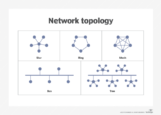
- Bus network. In the bus network topology, every node is connected in series along a single cable. This arrangement is found today primarily in cable broadband distribution networks.
- Star network. In the star network topology, a central device connects to all other nodes through a central hub. Switched local area networks based on Ethernet switches and most wired home and office networks have a physical star topology.
- Ring network. In the ring network topology, the nodes are connected in a closed-loop configuration. Some rings pass data in one direction only, while others are capable of transmission in both directions. These bidirectional ring networks are more resilient than bus networks since traffic can reach a node by moving in either direction. Metro networks based on Synchronous Optical Network technology are the primary example of ring networks.
- Mesh network. The mesh network topology links nodes with connections so that multiple paths between at least some points of the network are available. A network is considered to be fully meshed if all nodes are directly connected to all other nodes and partially meshed if only some nodes have multiple connections to others. Meshing multiple paths increases resiliency but also increases cost. However, more space is needed for dedicated links.
- Tree network. The tree network topology consists of one root node, and all other nodes are connected in a hierarchy. The topology itself is connected in a star configuration. Many larger Ethernet switch networks, including data center networks, are configured as trees.
- Hybrid network. The hybrid network topology is any combination of two or more topologies. Hybrid topologies typically provide exceptional flexibility, as they can accommodate a number of setups. For example, different departments in the same organization may opt for personalized network topologies that are more adaptable to their network needs.
A logical topology for a network refers to the relationship between nodes and logical connections -- defining how data should transfer.
A logical connection differs from a physical path when information can take an invisible hop at intermediate points. In optical networks, optical add-drop multiplexers create logical optical paths because the ADM hop is not visible to the endpoint nodes. Networks based on virtual circuits or tunnels have a physical topology based on the real connection medium -- fiber, for example -- and a logical topology based on the circuits and tunnels.
Sometimes, the logical topology refers to the topology as the user sees it. Internet Protocol (IP) and Ethernet networks are two common examples. They are fully meshed at the connection level since any user can connect with any other user. This is true unless some means of blocking unwanted connections, like a firewall, is introduced. Full connectivity is a property of the network protocols used -- IP and Ethernet -- not of the network topology itself.
As an example, logical bus and logical ring topologies can be used to define data transmission flows. A logical bus topology features nodes that broadcast data to the entire network. Other nodes on the network check to see if the data is meant for them. Logical ring topology only allows one node to transfer data at a time.
How do you diagram a network topology?
Diagrams of the network topology should be made before constructing a network. This way, network admins know what components constitute the network and how they interact.
This process should start with a list of all the devices in the network. This could, for example, include routers, firewalls and servers. The type of network topology should then be chosen. Once the list of devices is put together and a topology has been chosen, the diagram can be sketched out. Devices should be placed in areas that would best make sense, considering data flows. Next, lines are drawn from network devices. These lines are the connections the network nodes make. Stray away from having too many lines cross over each other and strive to make the diagram clear and easy to read. Scalability and future modifications should also be kept in mind when creating the diagram.
After a sketch showing a rough general input is constructed, diagram software can be used to help map everything out. The software used may include a network diagram template to follow. The network nodes should be named, and lines can be color-coded to further help make the diagram more understandable and clear.
What are examples of network topology tools and software?
There are many network topology tools available, including those that can be categorized as configuration and management tools, network performance software and network mapping software.
For instance, network configuration software helps configure networks, while also automating repetitive tasks. These tools are often used to configure complicated network topologies and can auto detect network nodes and highlight apparent vulnerabilities.
Network performance monitoring and troubleshooting tools keep track of and alert users to network-related performance issues and outages. Some of these tools may keep track of performance using a visual display of the network topology. After setting baseline performance settings, users can track, locate and troubleshoot issues.
Network topology mapping software aids in creating network topology diagrams. Examples of mapping tools and features are the following:
- Datadog live network mapping
- Edraw
- Lucidchart
- ManageEngine OpManager network mapping
- Microsoft Visio
- NetTerrain Logical
- SolarWinds Network Topology Mapper
- Spiceworks network mapping
Learn four network resiliency factors and what steps organizations can take to build redundancy into their networks.